Dock Installation
Overview
The instructions below are there to guide you with the installation of the Docks. These instructions can be used for table and surface area installs.
Requirements
| Requirments |
| No.4 Allen Key |
| 3/8 inch to 3/8 inch John Guest Fitting (Used to connect Beverage Pipe to Dock). The type may differ depending on install. |
| If pouring beer, the beverage in the lines being supplied to the Dock needs to be cold. Run the beer through a Flash Cooler, or store kegs in a cold room. Beer temp on the lines needs to be between 2 and 5 degrees, depending on beer being poured. |
| Please ensure that the kegs are stable and the beverage lines are balanced. Ensure that you have the right amount of pressure to pour at the desired speed, without foaming. A beer tech will be required to achieve this optimoly. Beer line calculator |
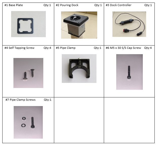
Components
Dock installation
| Image | Instruction |
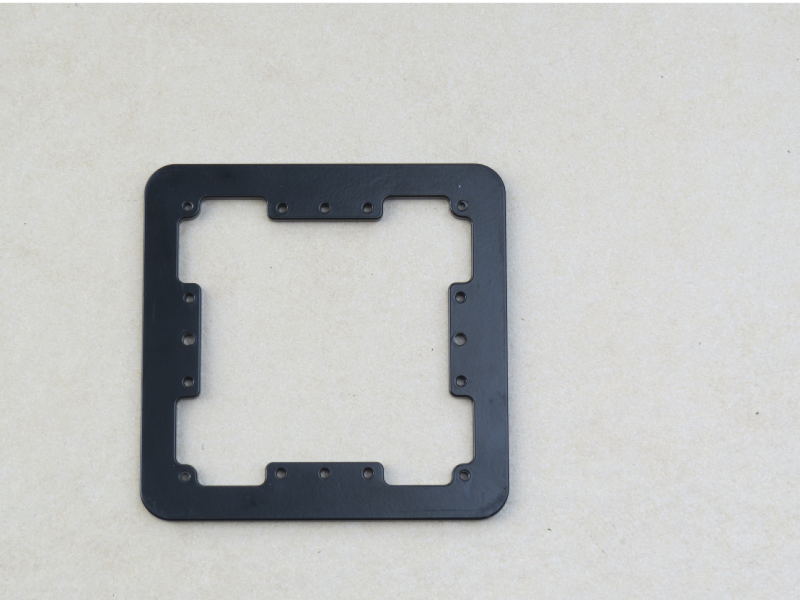 |
If installing on a solid surface. Use the Dock Base Plate as a stencil, to cut out the required shape. |
 |
If the surface is wooden, drill 2 pilot holes for the self tapping screws or drill larger holes to accommodate bolts. |
 |
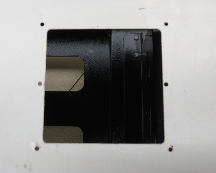
Attach the base plate to the surface using the required fasteners. |
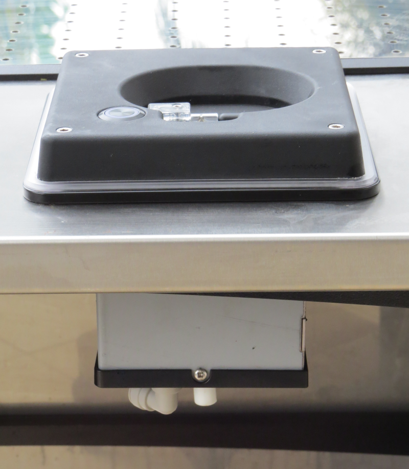 |
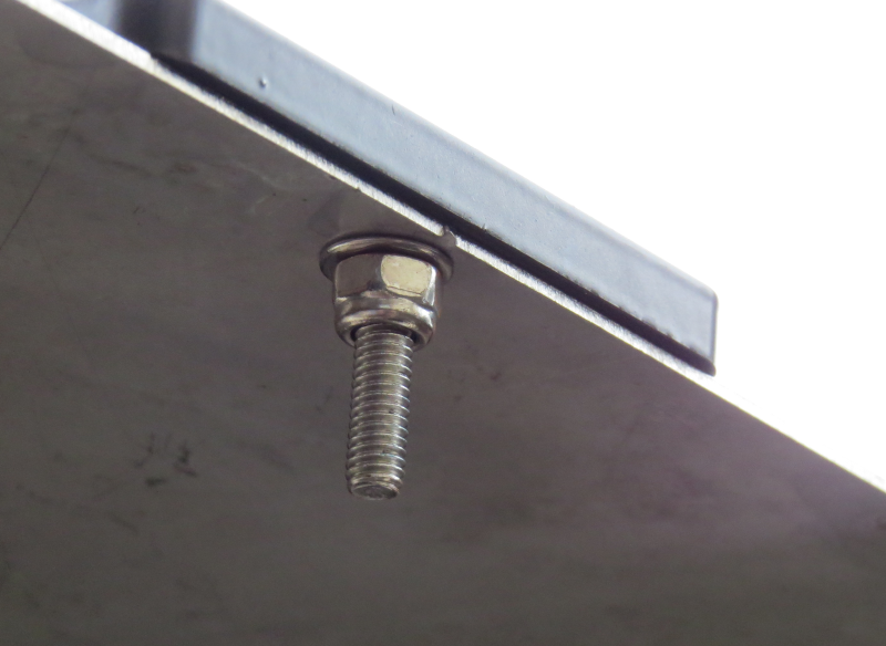
Secure the Dock to the base plate, using the 4 x SS Bolts, supplied with the 4mm Allen Key. Do not over tighten. |
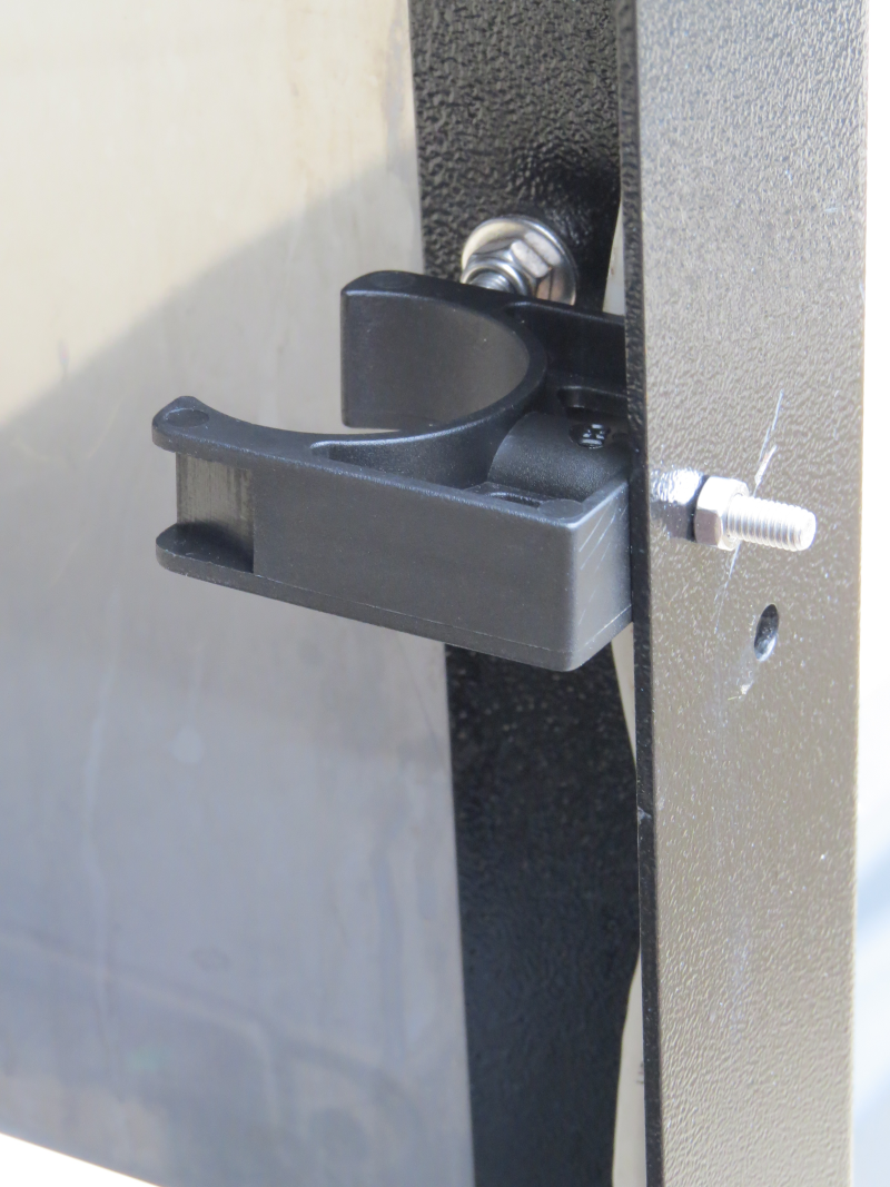 |
Secure the Pipe clamp to the table on the left and right leg, using the Xmm Bolts & Xmm Nut supplied. |
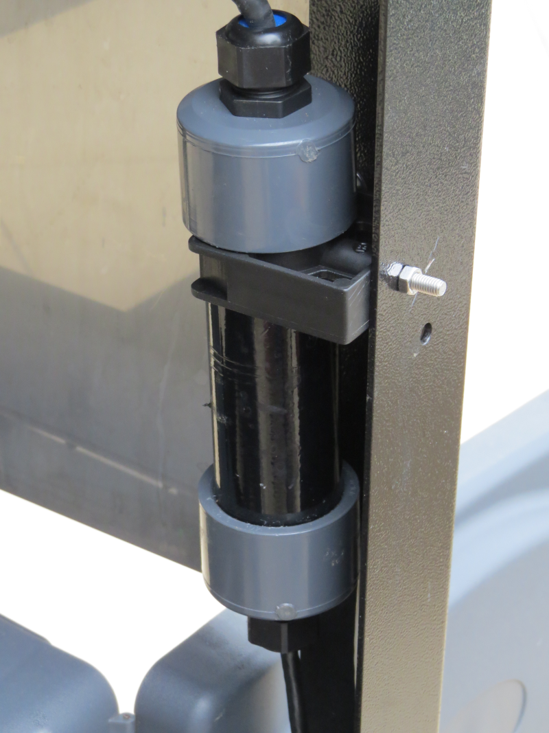 |
Secure the Dock Controller in the pipe clamp. |
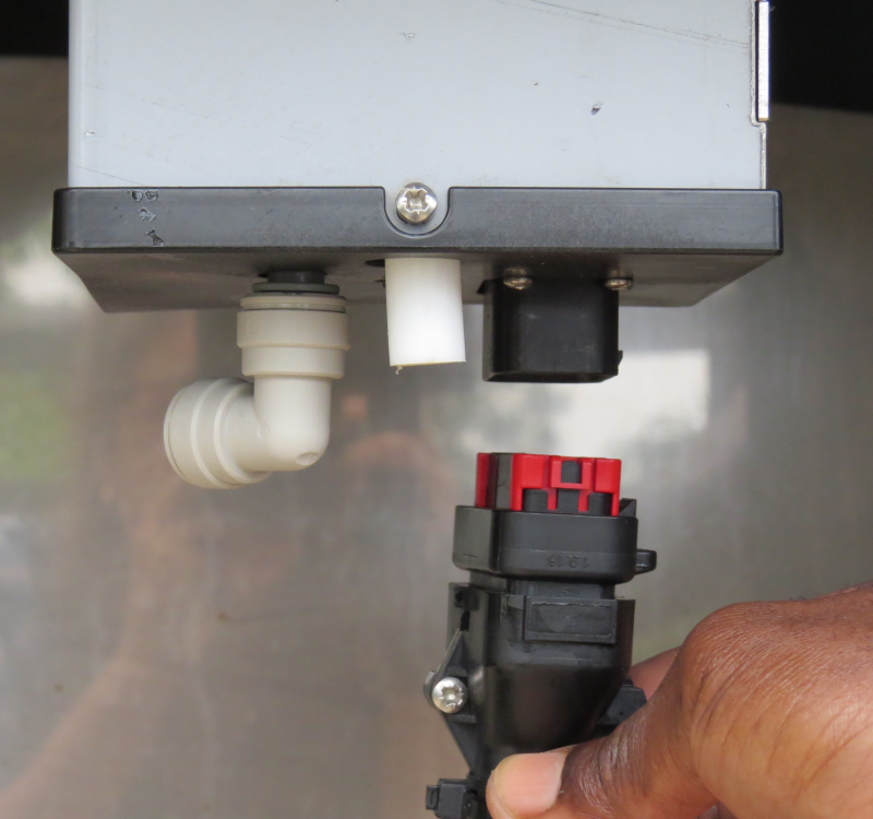 |
Plug the Control Electronics into the Pouring Dock. |
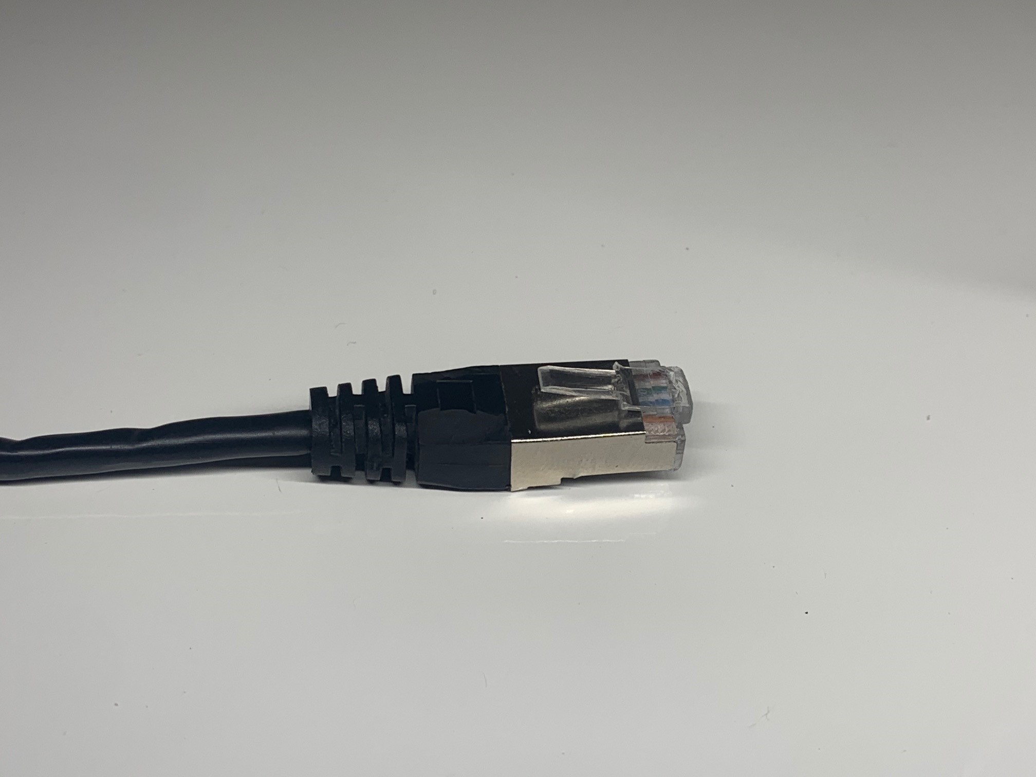 |
Prepare the ethernet cable that runs from the PoE switch to the location where the dock is being installed. If you are using a Table refer to the MasterPlug Box instructions.
Please ensure that there is no power running through the ethernet cable. Please ensure that you use a slimline ethernet boot, so that the connector can pass through the cable gland. |
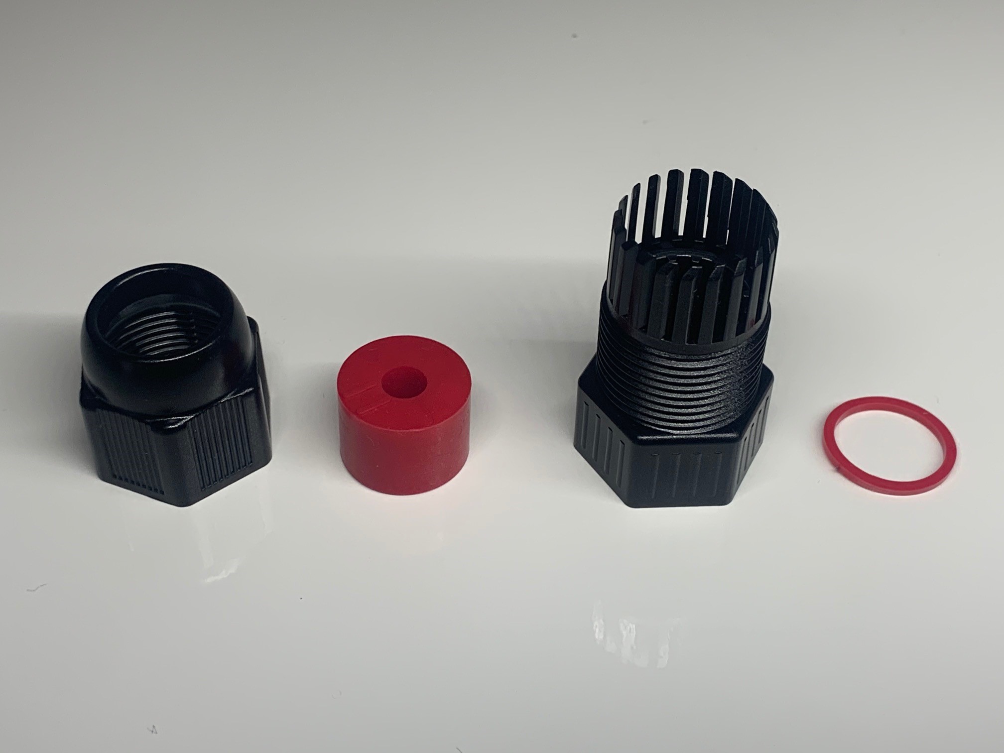 |
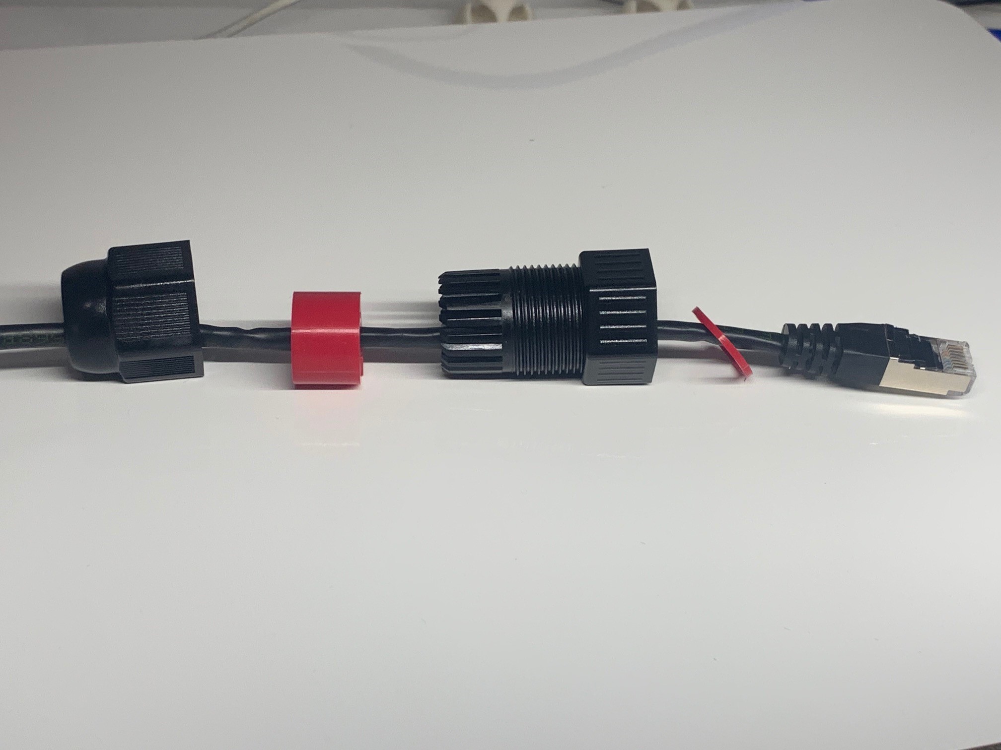
Unscrew the open end of the Ethernet Coupler and unscrew the cable gland cap and remove the grommet using the Allen Key. Becareful not to lose the provided o-ring. |
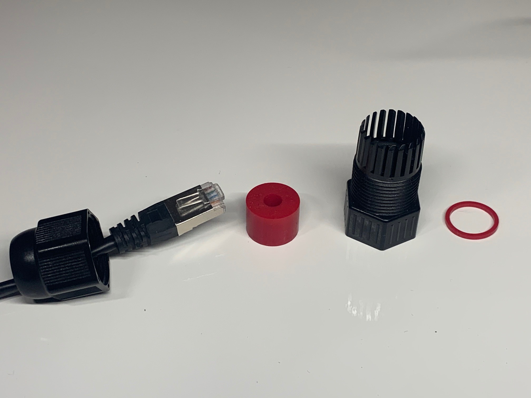 |
Thread the ethernet cable (That runs from the PoE switch) through the cable gland cap. |
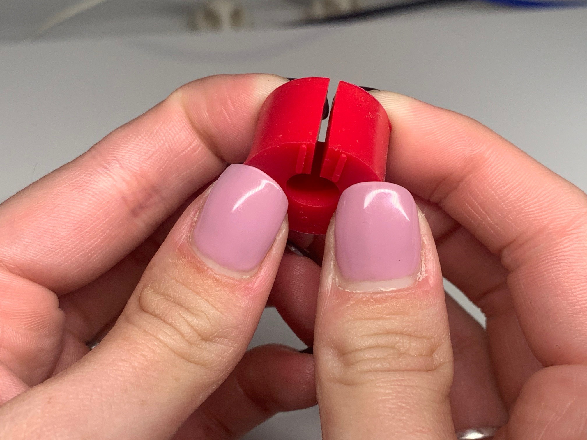 |
Gently part the grommet on the designated lines and wrap the grommet around the ethernet cable. |
 |
Thread the ethernet cable through the cable gland and push the grommet into place. |
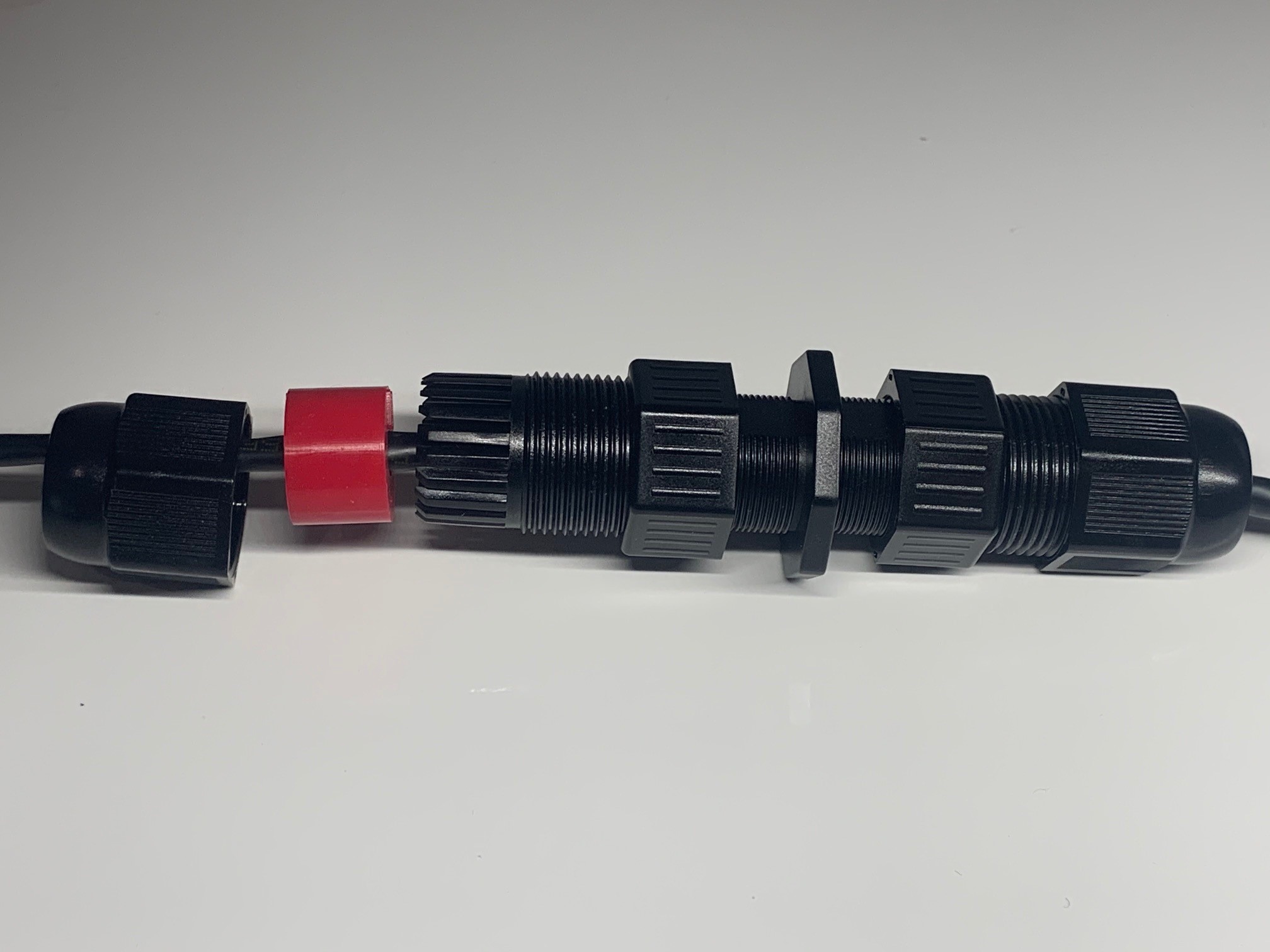 |
Insert the ethernet cable into the ethernet coupler, ensuring that the o-ring is in place and tighten the cable gland to the coupler. |
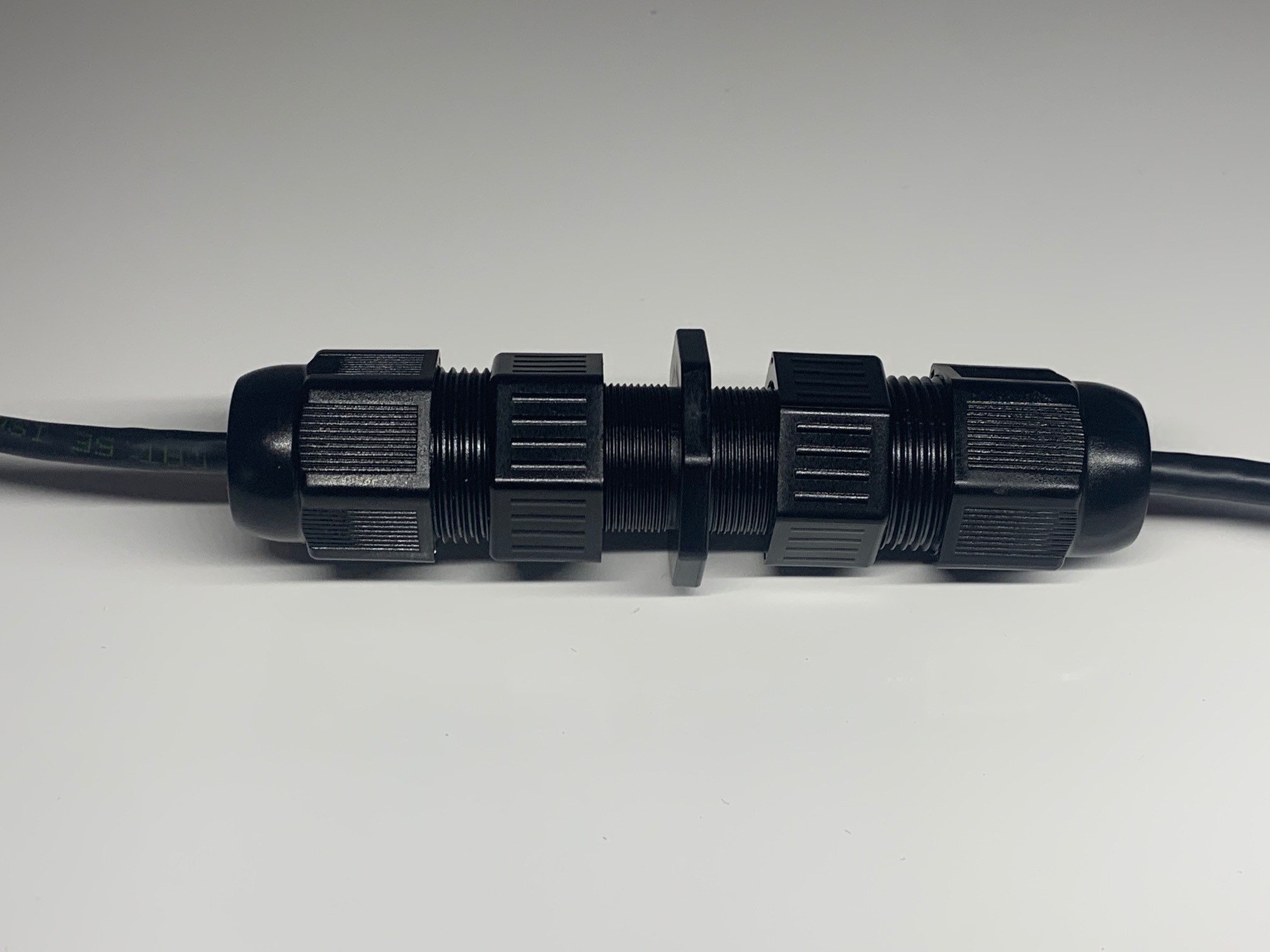 |
Push the grommet into place and tighten the cable gland cap. |
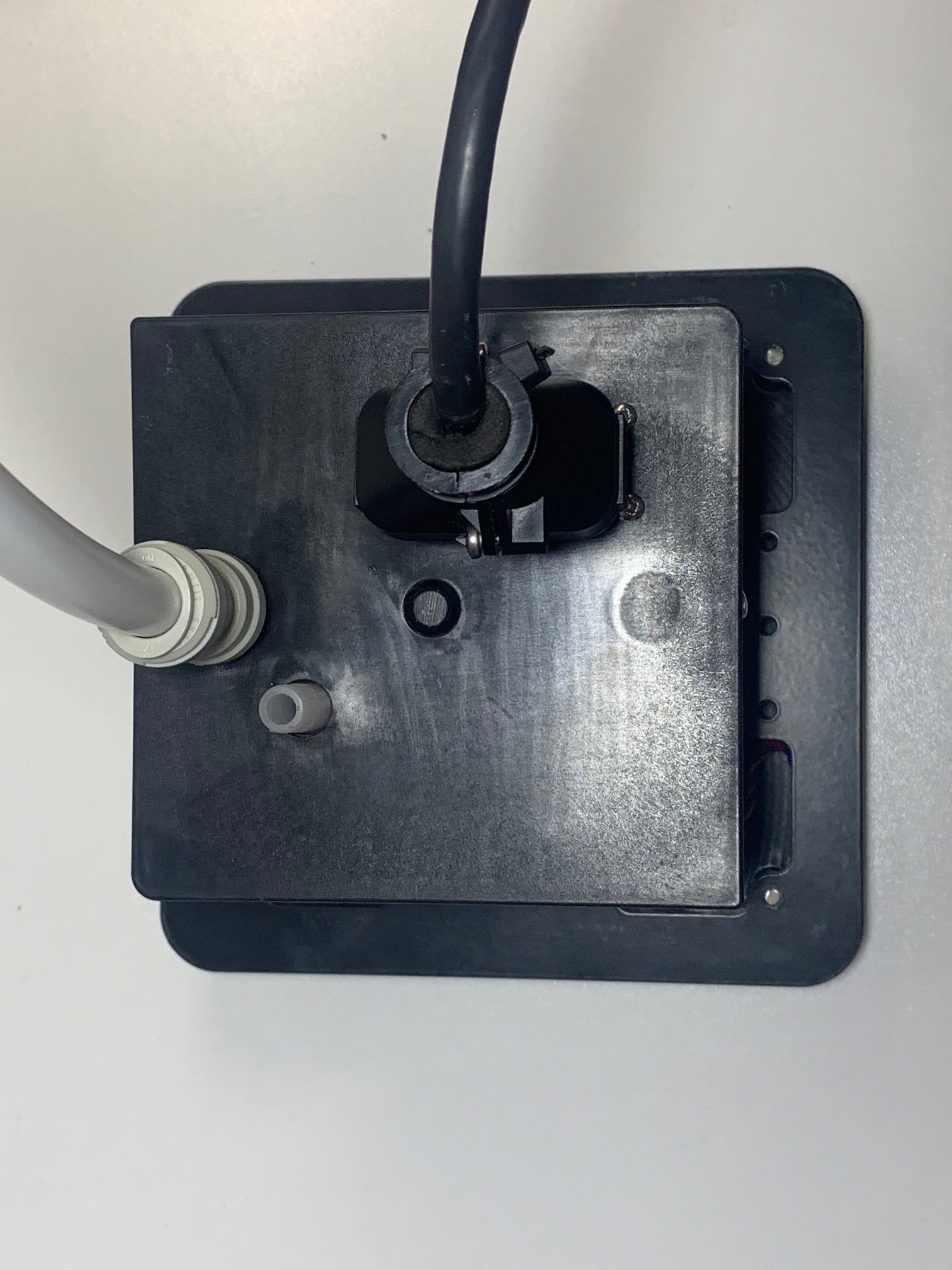 |
Connect Drainage Pipe to 1/2 inch pipe. Supports John Guest fittings |
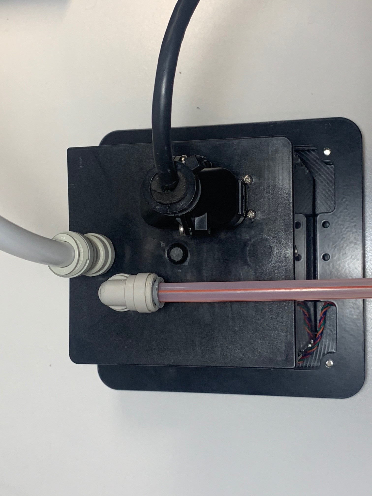 |
Connect Beverage Line using a 3/8 inch John Guest Fitting |